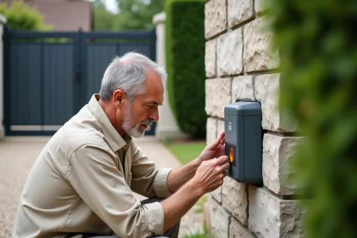
A flashing light on the control box of a Somfy electric gate is not a random failure. On recent motors (Slidymoove, Evolvia, 2MCC boxes), each sequence of flashes corresponds to a specific error code, documented by the manufacturer in its online manuals. Understanding this logic can prevent a premature call to the technician and sometimes restore functionality in just a few minutes.
Error code logic on recent Somfy boxes
Older Somfy motors only had a generic flashing light to indicate a malfunction. On current ranges, the LED on the electronic box acts as a true diagnostic tool. The number of successive flashes, separated by a pause, indicates a specific fault.
This correspondence table, once limited to paper manuals provided with the motor, is now accessible on Somfy’s support pages and in online FAQs. The principle remains the same from one model to another, even though some variations exist between Slidymoove 300, Slidymoove 600, and Freevia 400.
When you observe a flashing light problem on a Somfy gate, the first reflex is to count the exact number of flashes before the pause. A single flash does not have the same meaning as three or six consecutive flashes.
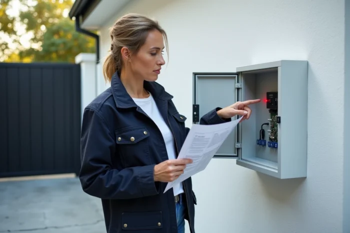
Meaning of LED flashes on Slidymoove and Evolvia
The most common codes cover the majority of situations encountered by users. Here’s what each sequence translates to on the latest generation Somfy boxes.
- One flash: the motor is operating on its backup battery, indicating that the 230 V mains power is cut off. Check the dedicated circuit breaker and the power cable.
- Two flashes: the box is waiting for self-learning of the stops. This is a normal state after a power reset or a reset. The gate must perform several complete open/close cycles before returning to standard operation.
- Three flashes: fault on the photoelectric cells. The problem comes from misalignment, faulty wiring, or an obstacle interrupting the beam.
- Five flashes: the thermal safety has been triggered because the motor has overheated. It must cool down completely before any further attempts.
- Six flashes: short circuit detected on an accessory output (flashing light, 24 V BUS, cells). The motor itself is not necessarily at fault.
The four-flash code varies by model. On a Slidymoove or Freevia 400, it indicates a short circuit on the START input. On older Freevia 280/290/300/600 models, it points to a fault on the BUS.
The trap of the 6 flashes code and 24 V accessories
The six-flash code deserves special attention. On recent Somfy boxes, the 24 V power supply is no longer systematically permanent for connected accessories (orange light, cells, intercom). A short circuit on one of these outputs is enough to block the entire gate, while the motor is perfectly operational.
Field feedback varies on this point: some users resolve the issue by temporarily disconnecting the flashing light or the cells to isolate the faulty accessory. Others find that a dedicated 220 V / 24 V transformer needs to be added to properly power an intercom or siren connected to the box.
Procedure for re-learning stops after a flashing light
Somfy has standardized, on the Slidymoove and Evolvia ranges, a mandatory procedure after any prolonged power cut or reset of the box. The status light continues to flash until the stops have been re-learned, and the gate refuses normal commands during this phase.
The procedure involves launching several complete open and close cycles, usually by holding down the remote control button. The gate then moves slowly, records its extreme positions, and then the light switches to a fixed mode. Only then does automatic operation resume.
A detail often overlooked: if an obstacle interrupts a learning cycle (forgotten trash can, stone in the track, stuck branch), the procedure must be restarted from the beginning. The box does not memorize a partial learning.
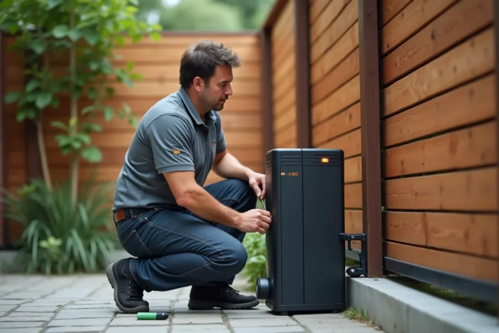
Diagnosis of the Somfy electronic board: when the light is no longer enough
Not all flashes lead to a simple solution. When the red light continues to flash after checking the mains, cells, and accessories, the problem is likely on the electronic board itself.
The capacitors in the control box are among the most vulnerable components, especially in installations exposed to voltage variations or storms. A swollen or burst capacitor can be visually identified by opening the box cover (after cutting off the power). Specialized repairers offer to restore these boards, which is cheaper than a complete replacement of the box.
Checks before concluding a board fault
- Disconnect all 24 V accessories (cells, flashing light, intercom) and restart a cycle: if the light returns to normal mode, the fault lies with the accessory wiring, not the board.
- Test the remote control with new batteries, or use the push button directly on the box to eliminate a radio transmission issue.
- Visually check the condition of the terminals: a loose or oxidized wire on the motor terminal can cause an error code identical to a board fault.
If after these checks the light persists in its error sequence, the electronic board is the most likely cause. The available data does not allow distinguishing a faulty capacitor from a damaged circuit board from a distance: only a physical examination of the board can determine this.
The most useful reflex in the face of a flashing light remains to note the exact number of flashes and consult the manual for your specific model. The codes are reliable, as long as you count rigorously. One flash too many or too few points to a completely different failure.